Nibe Heatpump Home Automation - WIP
I have an F1255-6 R Nibe heatpump + Triplesolar cooling module with SMO 20 or 40 controller in my home which I’d like to read out and possibly automate/optimize. Here I document my approach.
Intro 
I have a Nibe F1255-6 heatpump with SMO 40(?) control box.
Update firmware from here: https://www.nibe.eu/nl-nl/producten/smart-home/nibe-uplink-to-myuplink?HPModel=nibe-e10 (nibe.eu)
Goal 
- Show live performance of the heatpump (e.g. power/COP) during both heating and cooling
- Optimize consumption to either low electricity price (via epexspot (epexspot.com)) or low carbon intensity (via co2signal (co2signal.com)?)
- Optimize electricity consumption / COP by tuning parameters
Todo 
Why is the Triple Solar cooling module running almost always?
What is the difference between HW load and HW top? –> seems to be the location of the temperature sensor, one more at the bottom (load), one more at the top (top).
What is the optimal amount of degree minutes to trigger heating on? –> Now: -60DM and +100DM.
How can I measure the COP? (existing methods scale the theoretical COP based on specification & ambient temperatures)
What is a reasonable 12h idle temperature reduction for the 180L boiler? (How) can I reduce this? –> probably not easy to improve
How can I set passive cooling to start at lower temp than active cooling? –> don’t use, not useful
How can I reduce the internal heating element power to improve self-consumption or battery consumption (which have capped power)?
How/what energy use can I adjust to optimize low-cost energy? E.g. 60 degree cycle on specific day?
Get heatpump logic from Keje/Github
Get ‘Heat medium flow’ temp –> OK done
Get dump of nibe settings –> OK not possible easily
Explain filtertime –> OK understood
Check which PM2.5 source used –> https://aqicn.org/station/@367963/de// (aqicn.org) + https://aqicn.org/station/@373501/de/ (aqicn.org) https://community.home-assistant.io/t/openaq-air-quality-data/597059/2 (home-assistant.io) // https://explore.openaq.org/#12/52.10131/5.12819 (openaq.org) https://community.home-assistant.io/t/air-quality-meters/147655 (home-assistant.io)
Setting up hardware 
Hardware setup 
There’s a few (hardware) options for reading out the heatpump. I chose a pre-built LilyGO T-CAN485 ESP board (opencircuit.nl) with esphome-nibe (github.com). Other options are listed below
Raspberri Pi with Modbus 
Hardware (total: 52 EUR):
- RPi W (19 EUR (kiwi-electronics.com))
- RS485 Pi (18 EUR (kiwi-electronics.com))
- 12V input shim (15 EUR (kiwi-electronics.com))
Software: nibepi (github.com) OR using nibe (github.com) and nibe-mqtt (github.com) libraries
Arduino/ESP32 with Modbus (preferred) 
Hardware (total: 17-36 EUR):
- Arduino R3 clone (10 EUR (tinytronics.nl))
- Arduino R3 (25 EUR (tinytronics.nl))
- DFRobot RS485 shield (dfrobot.com) (11 EUR (tinytronics.nl))
- Grove RS485 (7 EUR (kiwi-electronics.com))
OR a combined board:
- LilyGO T-CAN485 (20 EUR (opencircuit.nl))
Software: esphome-nibe (github.com)
Pre-built PRODINo 
See here (kmpelectronics.eu) or here (web-engineering.info)
Installation 
For details, read the installer manual (nibe.eu). First remove the front panel of the heat pump with the two TX25 Torx screws at the bottom, then tilt the panel and lift up (see page 8 of the installer manual (nibe.eu)). See page 12 for the location of the distribution boxes, and page 20 on how to open it (specifically: box AA3). Below a few pictures of my setup
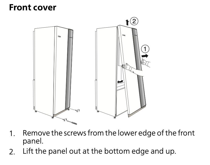
Removing front panel from NIBE F1255 heatpump
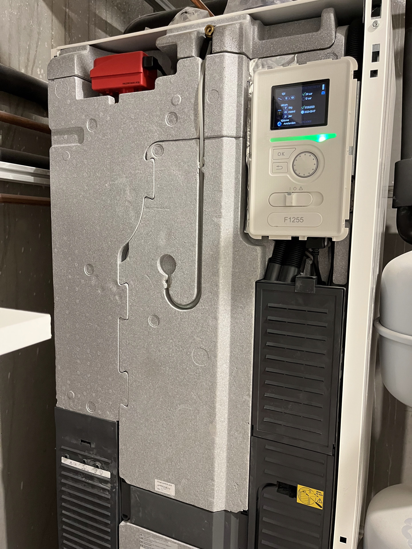
NIBE heatpump with front cover removed
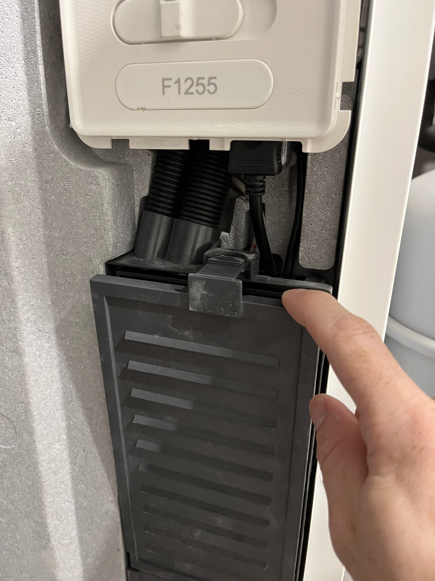
Distribution box AA3 opening latch
An overview of electrical diagrams is available here (nibe.eu) (Dutch). here, you can see you need to connect 9-10-11-12 (GND-B-A-12V) on print AA3 rail X4. Alternatively, see the Nibe Modbus moduledocumentation (nibe.eu), or this topic (energiesparhaus.at). In my case there was already a wire connected to the pins (blue/yellow/green/orange wires to 9/10/11/12 = GND/B/A/12V), but it was not connected on the other side (?). I used this to connect my LilyGo.
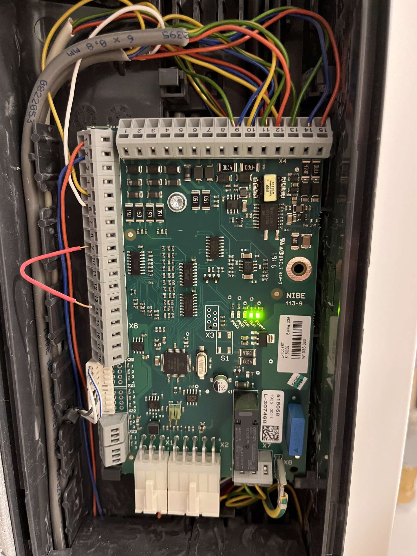
Distribution box AA3 opened, showing the connector rails X6 (left) and X4 (top)
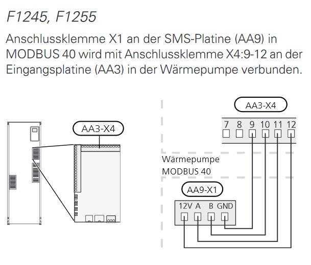
Connection scheme for the MODBUS40 accessory, using pins 9-10-11-12 to GND-B-A-12V on MODBUS. I used the blue/yellow/green/orange wires that were already available.
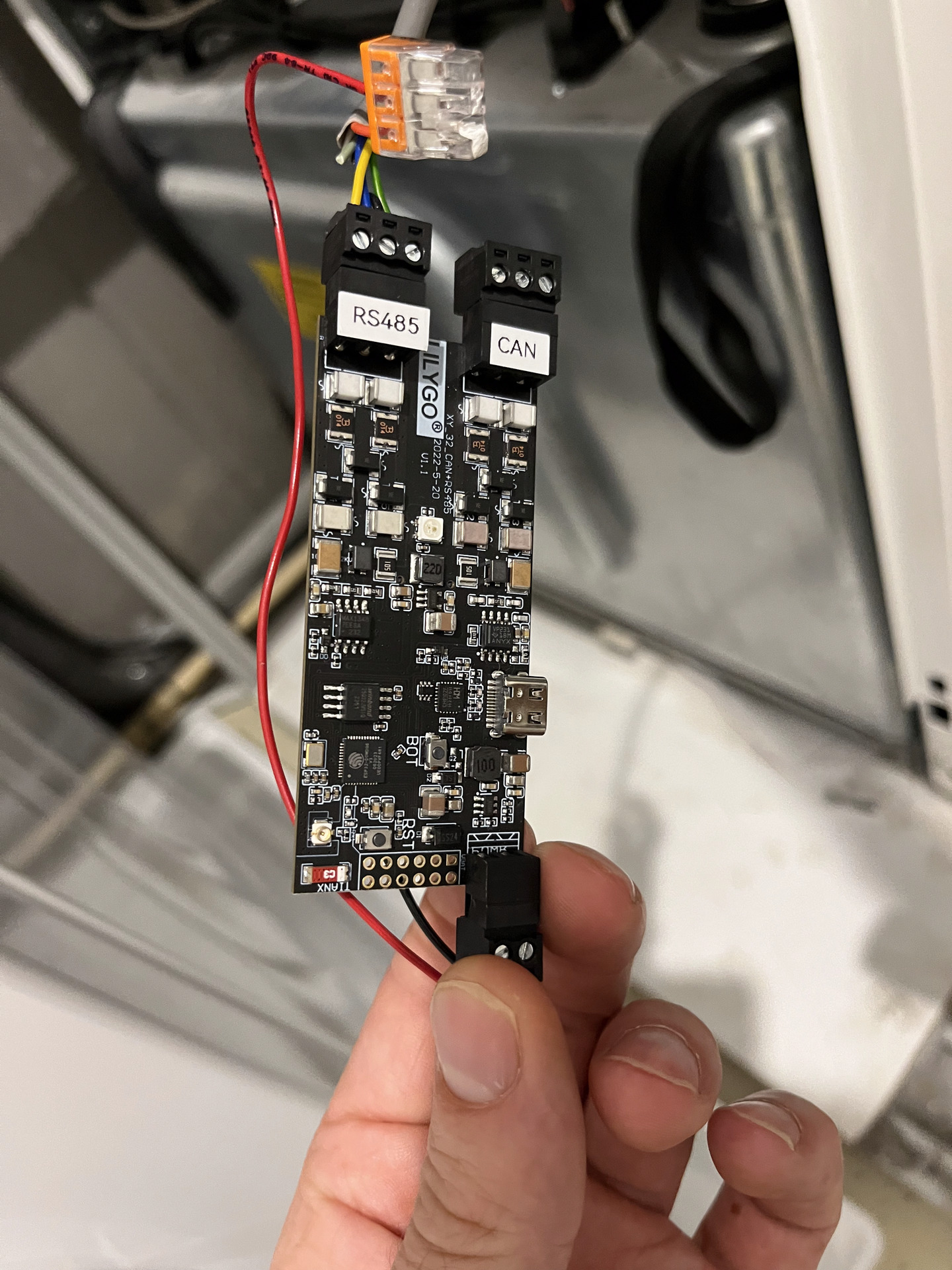
Connection to LilyGO-T CAN485 ESP board.
Software setup 
For the LilyGO T-CAN485 ESP board with esphome-nibe combination I chose, I combined the default esphome config template with the LilyGO example (github.com) config of esphome-nibe. This connects to the heatpump via modbus and sets up a UDP daemon for interfacing, which can be read out via nibe_heatpump (home-assistant.io) integration on Home Assistant. You can add this addon and then connect to the LilyGO board by choosing ‘NibeGW’ and fill in the remote address of your esphome
Reading out diagnostics 
Determining diagnostics 
Once you have a hardware setup for modbus, you can read out certain ‘coils’ which are diagnostics parameters, see e.g. this list of parameters (github.com) (F1155/F1255 (github.com) specifics). In my case many of the >100 parameters were not active. You can plug in a USB stick as well which prints a log file and allows you to
Translation tables - WIP 
Translation table for eb100_ep14_pca_base_relays_43514:
- 3: off
- 7: heating/cooling
- 15: hot water
- 0/1/2/3/6/9/11/14: ??
Sensor values 
Data about the glycol/water mix to your roof (PVT) or ground loop
- Brine in: sensor.eb100_ep14_bt10_brine_in_temp_40015
- Brine out: sensor.eb100_ep14_bt11_brine_out_temp_40016
- Brine pump speed: sensor.ep14_gp2_brine_pump_status_ep14_43439
Data about the flow to your (underfloor) heating and hot water line
- Heat medium flow: sensor.bt2_supply_temp_s1_40008 ??
- Return temp.: sensor.eb100_ep14_bt3_return_temp_40012 ??
- Pump speed heating medium: sensor.supply_pump_speed_ep14_43437
- Calculated Flow Temp: sensor.calc_supply_s1_43009
- Actual Supply Temp: sensor.bt25_ext_supply_40071
- Actual Return Temp: sensor.bt25_ext_supply_40071
Compressor related data
- Hot gas temp: sensor.eb100_ep14_bt14_hot_gas_temp_40018
- Suction gas: sensor.eb100_ep14_bt17_suction_40022
- Liquid Line: sensor.eb100_ep14_bt15_liquid_line_40019
- Condensor out: sensor.eb100_ep14_bt12_condensor_out_40017
- Current compr. frequency: sensor.compressor_frequency_actual_43136
- Compressor power: sensor.compr_in_power_43141
- Internal el. add. power: sensor.int_el_add_power_43084
Thermostat & hot water data
- Room temperature: sensor.bt50_room_temp_s1_40033
- Outdoor temp.: sensor.bt1_outdoor_temperature_40004
- Hot water temp.: sensor.bt6_hw_load_40014
- Hot water temp. (@ top): sensor.bt7_hw_top_40013
- climate system: climate.climate_system_s1
Settings (to control hot water charging by changing from economy to luxury)
- hot water mode: select.hot_water_comfort_mode_47041
- start temp luxury: number.start_temperature_hw_luxury_47043
- stop temp luxury: number.stop_temperature_hw_luxury_47047
Calculate COP 
From https://gathering.tweakers.net/forum/list_message/77230924#77230924 (tweakers.net) Based on syntax of this post (tweakers.net) and content of this post (tweakers.net) (see also here (tweakers.net) and here (home-assistant.io)). I added a x100 such that the unit percentage is correct (actual COP is a coefficient, but not sure how to show that unitless in HA):
  - sensor:
      - name: "Nibe F1255 COP Heating"
        unique_id: "nibe_f1255_cop_energy_heating"
        unit_of_measurement: "%"
        state: >
          {% set cop0035 = 4.72 | float %}
          {% set cop0045 = 3.61 | float %}
          {% set cop1035 = 6.49 | float %}
          {% set cop1045 = 4.79 | float %}
          {% set bt2 = float(states('sensor.bt2_supply_temp_s1_40008')) %}
          {% set bt3 = float(states('sensor.eb100_ep14_bt3_return_temp_40012')) %}
          {% set bt10 = float(states('sensor.eb100_ep14_bt10_brine_in_temp_40015')) %}
          {% set bt14 = float(states('sensor.eb100_ep14_bt14_hot_gas_temp_40018')) %}
          {% set bt17 = float(states('sensor.eb100_ep14_bt17_suction_40022')) %}
          {% set t_cop_helper = (45-35)*(bt2-35)/100 %}
          {% set tb_cop_helper = bt10/10 %}
          {% set copm = (1-t_cop_helper) * cop0035 + t_cop_helper * 3.61 + (1-t_cop_helper) * (cop1035 - cop0035) * tb_cop_helper + tb_cop_helper * (cop1045-cop0045) * t_cop_helper %}
          {% set bt14minbt2abs = (bt14 - bt2 ) | float | abs  %}
          {% set bt17minbt10abs = (bt17 - bt10) | float | abs %}
          {% set coptboven = (5 - (bt2 - bt3) ) / 2 %}
          {% set copt = 100 * copm * ( 1 - ( coptboven / (bt2 - (5.0/2) + bt14minbt2abs - ( bt10 - bt17minbt10abs  ) ) ) ) | round(0) %}
          {% if states('sensor.prio_43086') != 'OFF' %} {{ copt }} {% else %} 0.0 {% endif %}
Understanding Nibe control/automation - WIP 
Cooling starts late 
- 1.1.2 koeling temp 22 deg
- 1.2.2 program: 17:00-9:00 @ off
- 1.9.1.2 koeling curve 50 - 25 deg @ 17 deg, then ramp to 20 deg @ 20 deg outside
- 1.9.2 ext instelling verwarming: 20.0 deg / koeling 20.0 deg –> ??
- 1.9.3.2 koeling min aanvoer temp 17 deg
- 1.9.4 factor verwarming: 2.0 / koeling: 1.0
- 1.9.5 koeling koel/verw sensor: BT50 / inst pt-wrd koel/verw-sensor: 21 deg / verw. bij ondertemp. kamer 1.0 deg / koeling bij overtemp. kamer 1.0 deg / passieve koeling @ 10 GM / actieve koeling @ 60 GM / stapverschil compressor 30 GM / tijd t. scahekelen warm/koel @ 0uur
- 4.9.2 start koeling 21 deg / stop verwarming 15 deg stop bijverwarmen 0 deg / filtertijd 1uur
- 5.1.9 dT-koelen 5deg –> ??
20240908 11:00
- temp climate system S1: 24.3 deg
- outdoor temp: 21.2 deg
- cooling off
Options (from Nibe (nibe.eu) (pdf (nibe.eu))) 20240908 12:00
- 4.9.2 Reduce ‘start koeling’ temp, 15 deg/18 deg, starts earlier, filter tijd 24h (to ensure we’re really in summer/winter before we start)
- 1.9.4 factor verwarming: 2.0 / koeling: 0.0
- 1.9.5 koeling koel/verw sensor: BT50 / inst pt-wrd koel/verw-sensor: 22 deg / verw. bij ondertemp. kamer 1.0 deg / koeling bij overtemp. kamer 1.0 deg / passieve koeling @ 10 GM / actieve koeling @ 60 GM / stapverschil compressor 30 GM / tijd t. scahekelen warm/koel @ 0uur
Options from GoT 20240909 14:30
- 1.9.5 Disable room sensor
Options 202409xx xx:xx
- Re-enable room sensor
Options 202410xx xx:xx
- Disable room sensor to optimize heating curve It seems
Tweaks & improvements 
- Shield outdoor temp sensor
- Optimize curve
- https://gathering.tweakers.net/forum/list_message/73300226#73300226 (tweakers.net)
- https://gathering.tweakers.net/forum/list_message/74457864#74457864 (tweakers.net)
- Understanding control scheme
- https://gathering.tweakers.net/forum/list_message/77201572#77201572 (tweakers.net)
- https://gathering.tweakers.net/forum/list_message/69678898#69678898 (tweakers.net)
- https://www.nibe.eu/nl-nl/kennisbank/video/nibe-instructievideo-s/nibe-werking-graadminuten (nibe.eu)
20241011:
- Use room sensor (1.9.4 @ factor 2)
- Set heating 1.3.1 schedule to heat to 13 deg at night, 21 deg during the day
- Observation: heat pump still operates during the night, as degree minutes still reduce, even if room temp is » set point temp.
20241105 22:30:
- Disable room sensor
- Disable heating schedule
- Set room temperature (1.1.1) to 0
- Observation: calculated supply temp goes to 24 degrees, degree minutes decrease rapidly, compressor power increases, heating the house too much.
20241106 12:00:
- Decrease heating curve from 2 to 1.
- Observation: degree minute was still at -600, calculated supply temp reduces, compressor power moderates. Perhaps this works if it didnt start with a degree minute deficit of -600.
20241107 16:00:
- Decrease heating curve offset from -1 to -2.
20241112 23:50
- Temperature is stable, upstairs a bit cooler than downstairs
- Set start engy sce prio 1 to -60 (4.9.3)
- Set 10:30 - 16:30 program to -1 (instead of -2)
20241214 23:00
- Set minimum heating flow temp to 15deg (was 20deg)
Tijdsvak | Koelcurve | Programma | Buitentemp | Binnentemp data | Binnentemp gevoel 
20241112 23:50 | C1-2 | 11-17: -1 | 5-10deg | 21.1deg | Koel
Tweaks & improvements - waterzijdig inregelen 
20241112 23:50
- Reduce flow in mimas1-4 (from ~0.5 to 0.4) & mimas1-1 (from 0.9 to 0.6) to increase the temperature (and decrease others)
20241113 12:20
- Made error in previous calibration: reduction in flow leads to lower temperature. Reset mimas1-4 and mimas1-1 to max open.
- Reduced flow in mimas1-7 and mimas1-2.
- Reduced flow in mimas-1, check mimas-4 is open.
20241114 19:40
- Reduce flow in mimas-1 & mimas-5 to lower temp –> check labeling is correct
Separating hot water & heating energy - WIP 
Not possible in InfluxDB (stackoverflow.com), as data are spread across two measurements.
SELECT state,energy FROM
  (select first(value) as energy from energyv3 where source='nibe' and uniqueid='compr_in_energy_43141' group by time(30m)),
  (select value as state from systemv3 where quantity='eb100_ep14_pca_base_relays_43514')
  WHERE time>now()-1d GROUP BY TIME(30m)
Post-processing in Python
# Approach one: grouped
energy = select first(energy) group by time(5m)

mask_hw = (pca == 15)
mask_heat = (pca == 7)

energy
Calibration of power usage 
There are two sensors giving power:
- compr_in_power_43141: heat pump compressor power
- int_el_add_power_43084: resistive heater
Using a Riemann integration sensor in Home Assistant gives me energy use (ensure to use left integration, although trapezoidal should work better it doesn’t).
Automating / optimizing 
There’s a few ways to optimize a heatpump
- Heating curves - determining heating circuit temperature depending on outside temperature
- Timing - optimize consumption by price / CO2 intensity / PV production
- Calibrating heating circuit (‘Waterzijdig inregelen’) - ensuring optimal heat transfer of the heating circuit
Optimizing curves 
TODO
Run boiler at lowest price point during the day 
Rationale: consume depending on electricity price
- Use the built-in smart price adaptation (nibe.eu) –> NOK prefer to run without vendor / proprietary cloud dependency
- Use hard-coded schedule based on average electricity prices over the day –> OK, works for 80% of cases
- Use dynamic control via e.g. Home Assistant –> OK, see below
Using ha_epex_spot (github.com):
Create template sensor (home-assistant.io) when to start during the day (11:00-17:00), requiring 1:30 to heat the boiler.
template:
  - trigger:
      - platform: time
        at: "00:00:00"
    action:
      - service: epex_spot.get_lowest_price_interval
        data:
          earliest_start: "11:00:00"
          latest_end: "17:00:00"
          duration:
            hours: 1
            minutes: 30
        response_variable: resp
    sensor:
      - name: Start boiler
        device_class: timestamp
        state: "{{ resp.start is defined and resp.start }}"
Now create automation based on this new sensor
trigger:
  - platform: time
    at: sensor.start_boiler
condition: []
action: []
Algorithm options
- high or low consumption (if price is negative, increase target temperature)
- time of boiler run –> run at cheapest our
- Control of run –> toggle target temperature, set 20 deg for idle and »20deg when needing to run
Algorithm #1
Default economy mode: start @ 42 deg, stop @ 48 deg Custom economy mode
- off/default: start @ 20 deg
- At lowest spot price on the day:
- if spot price < 0: start @ 50 deg, stop at 60 deg
- if spot price > 0: start @ 42 deg, stop at 48 deg
Algo #2
AT epex_spot.get_lowest_price_interval if price negative turn on high power else turn on regular delay 1 hour if price negative turn on high power else turn on regular delay 1 hour turn to idle
By PV production 
Rationale: consume depending on local electricity production. This is close to the above, except less at night and more during the day.
Sources 
- NIBE L/W warmtepomp optimalisatie (tweakers.net)
- Haal meer uit je NIBE warmtepomp met nibepi (tweakers.net)
- COP berekening voor Nibe warmtepompen (tweakers.net) – NB this is not really COP, but COP scaled from specs based on working point.
#ESP8266 #Heating #Home-Improvement #Linux #Server #Smarthome #Unix