DIY Jaga Dynamic Boost Hybrid (DBE/DBH)
(Updated: )
I have Jaga radiators in my home, which are of the type hot-water baseboard (wikipedia.org) making them great low-thermal momentum, high power density radiators, especially compared to (jaga.com) panel radiators (wikipedia.org). In this article I build my own temperature-controlled fans on top of these to increase the power and reduce heating lag even more. Cost is ~60€ per 70cm unit with 7 fans, compared to 300€ for Jaga’s version and only 3 fans for Speedcomfort’s version.
Contents
Introduction 
Jaga sells ready-made fan modules called DBH (jaga.com) (Dynamic Boost Hybrid), which replaces the older DBE (Dynamic Boos Effect) modules. These come with a control and sensing unit, but are fairly expensive at ~300€ per meter. Alternatively there’s a company called Speedcomfort (speedcomfort.com) which make their own version, but they’re more aimed at panel radiators instead of the Jaga baseboard radiators, and only have 3 fans which means it’s louder or has less airflow.
Since I like the challenge and learning, I decided to make these myself, greatly inspired by the Gathering of Tweakers forum thread (tweakers.net) on this topic.
Requirements 
- 20 year lifetime @ 200 days heating per year
- @ 10 switches per day: >40 000 switches (ideal: >100k)
- @ 10 hours per day (=2000 hr/yr): > 40k hrs MTBF (ideal: >100k hrs)
- <5 €/yr per radiator running cost
- @ 0.25 €/kWh: <10W per radiator
- Double inflow-outflow ∆T versus no fans
- Silent, cannot hear when reading on couch
TL;DR - instructions for the impatient 
- Prepare aluminium frame
- Mark out fan holes with the fans in place (e.g. using a screw to scratch in the aluminium)
- Drill 5mm holes to mount the fans (needs to be somewhat precise)
- Saw out approximate fan blade area (to have unobstructed airflow)
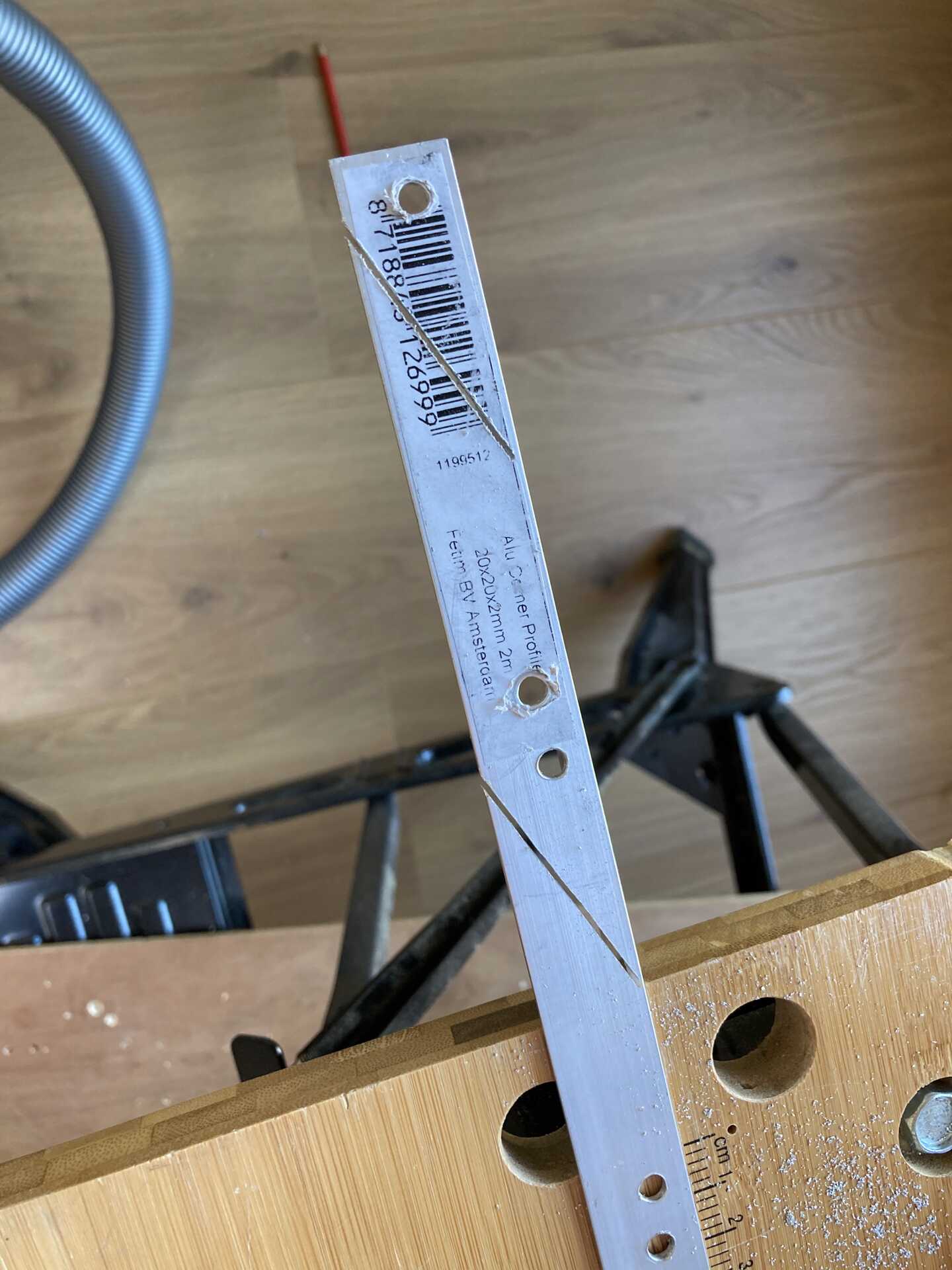
- Drill holes in the side wall of the frame to fix the wires on
Marking out fan holes on aluminium frame
Drilling out fan holes & sawing out fan blade area for improved airflow
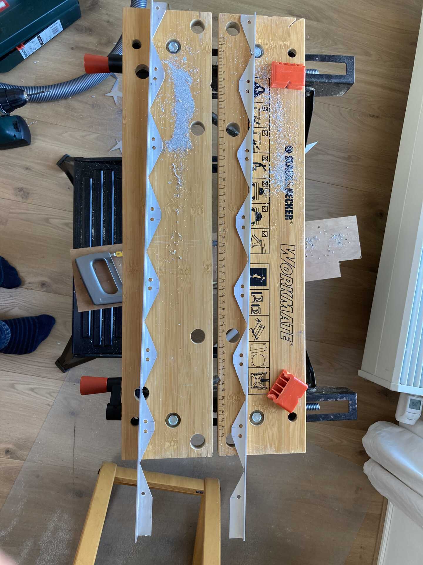
End result of two alumiunum frame with sawed out fan blade area
- Mount & connect the fans
- Mount the fans in the frame using supplied screws or M4 bolts
- Wrap the cable around the fan to prevent dangling
- Connect the cable to the essential molex fan plug splitter (hardwarewebwinkel.nl)
- Fix the cables to the hole in the side-wall drilled previously
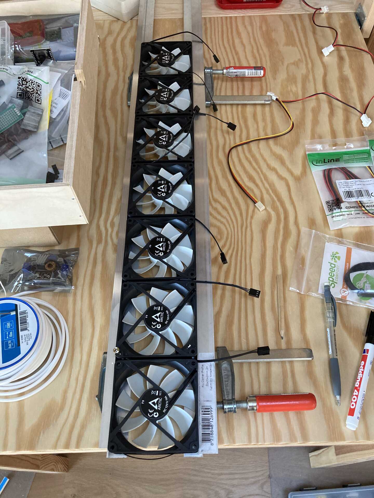
Mounting the fans in the frame
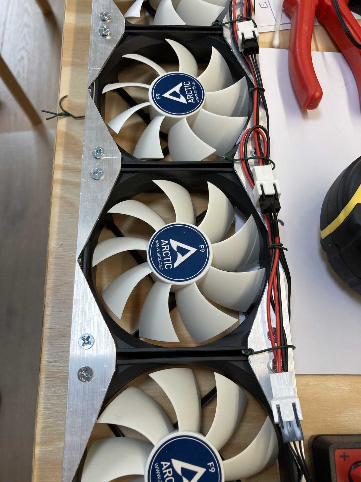
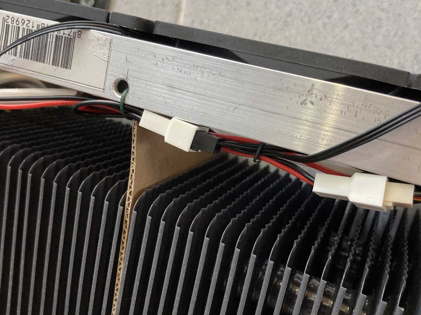
Connecting and fixing the cables
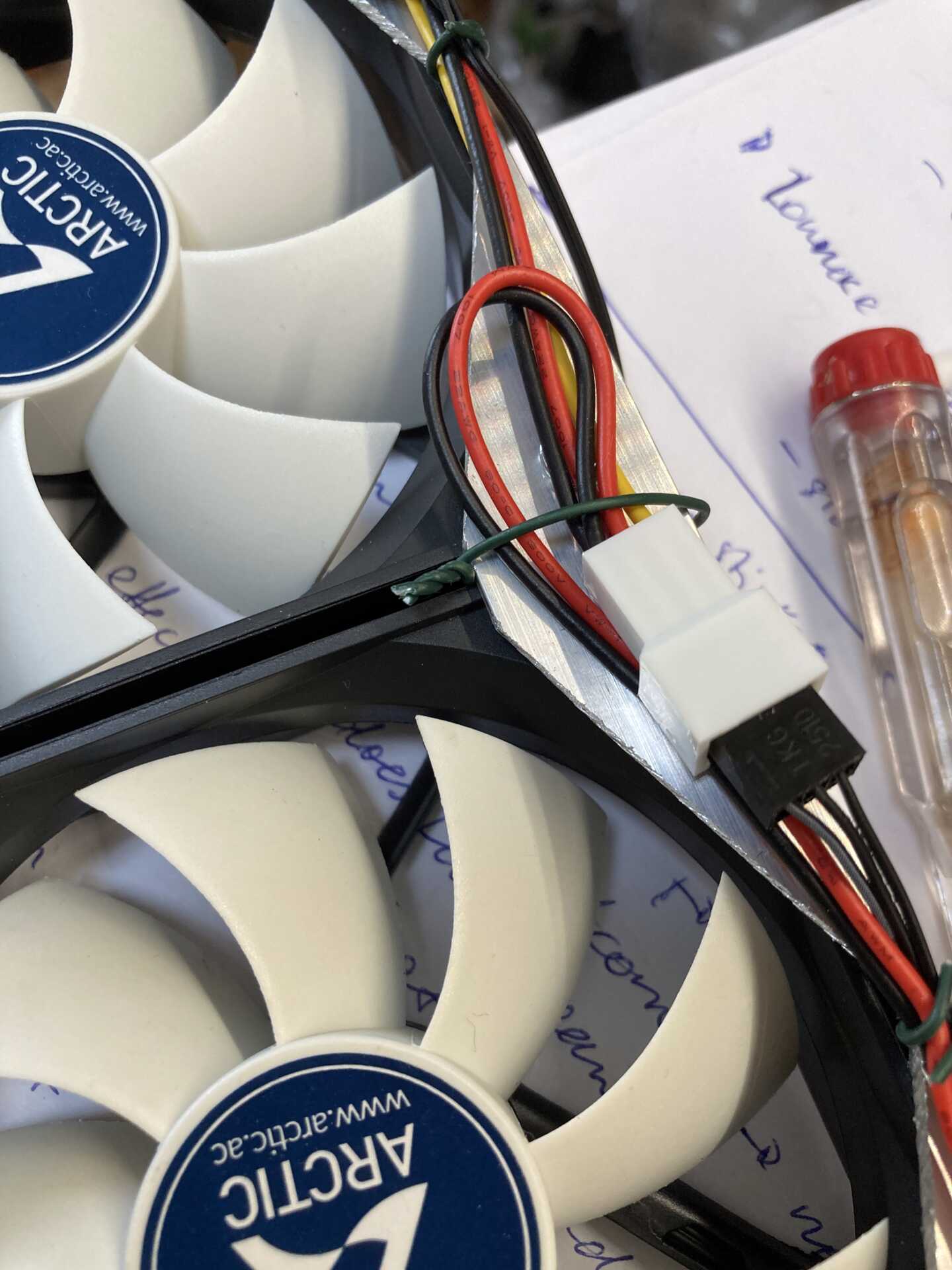
Close-up of cable management
- Make the controller, connect power
- Take a ~15cm piece of aluminium profile to mount the step-down converter (tinytronics.nl) and power supply (tweakers.net)
- Mount the DC jack connector (tinytronics.nl) to connect the thermostat switch (speedcomfort.nl)
- Use the switch to break the positive polarity from the power supply, such that the step-down converter is not connected to live power when not operating.
- N.B. I mounted the controller + power supply away from the radiator (because of space and splash risk), such that I have 2 double-polarity cables running from the control unit to the radiator: 1 is for the thermostat switch, the second is for the 12-V power.
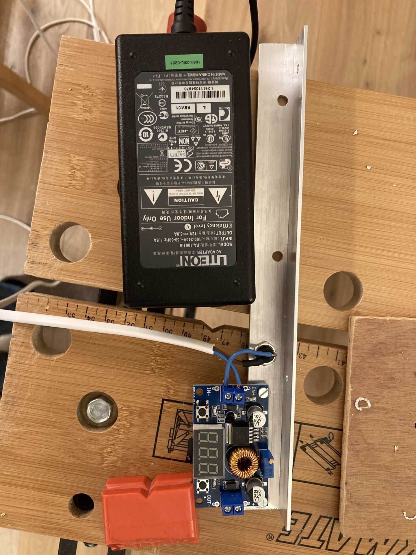
Frame for controller and power supply
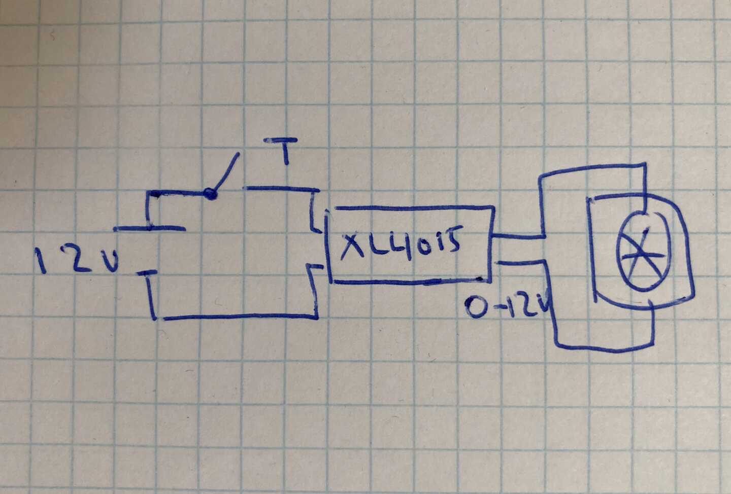
(Logical) wiring diagram for power supply, switch, and step-down converter
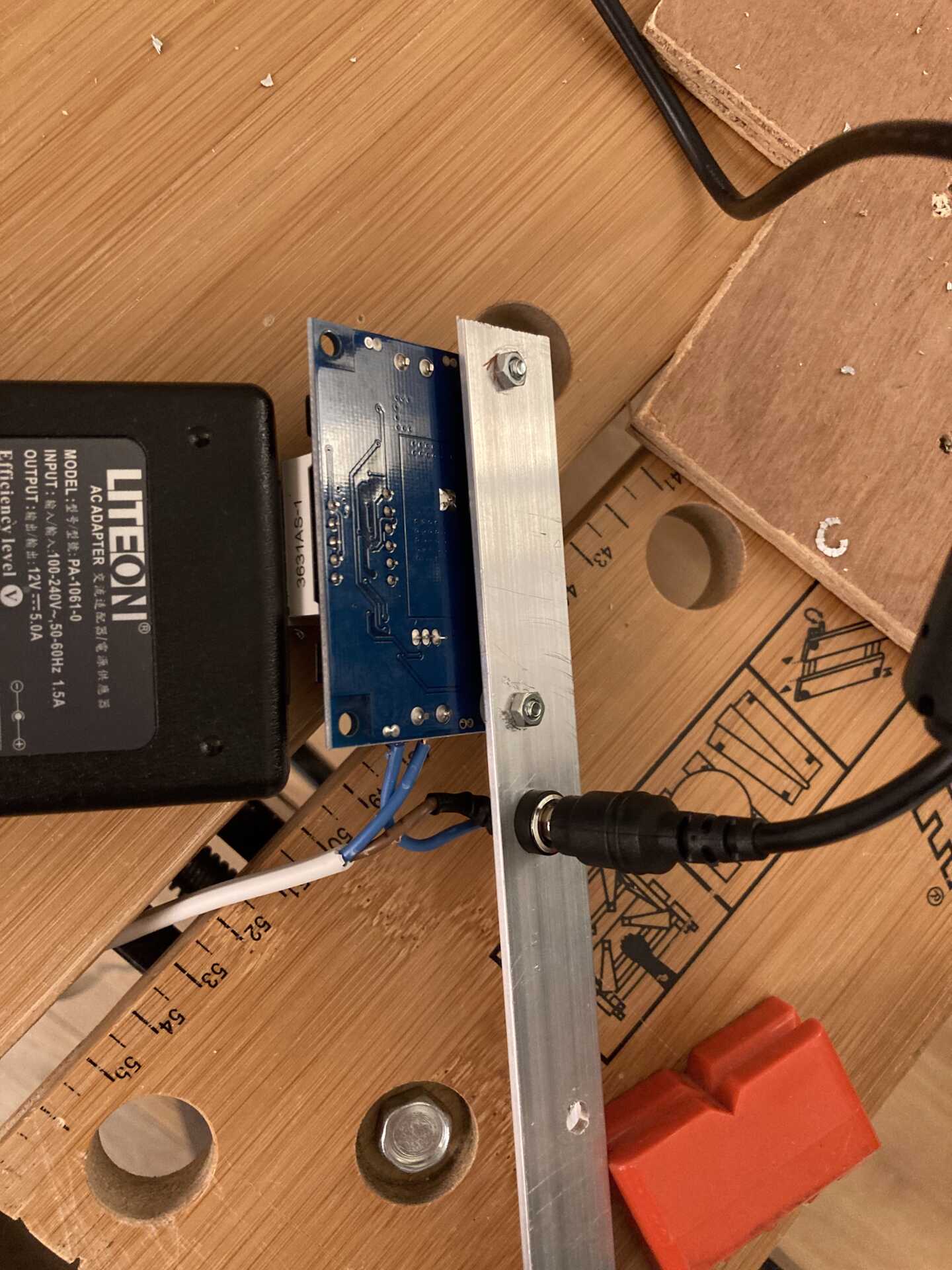
Frame for controller and power supply
- Make support structure & installing
- To reduce noise slightly, I made a spacer between the radiator and fan out of cardboard.
- Simply cut to shape using scissors.
- Place in between fans to minimize airflow interference.
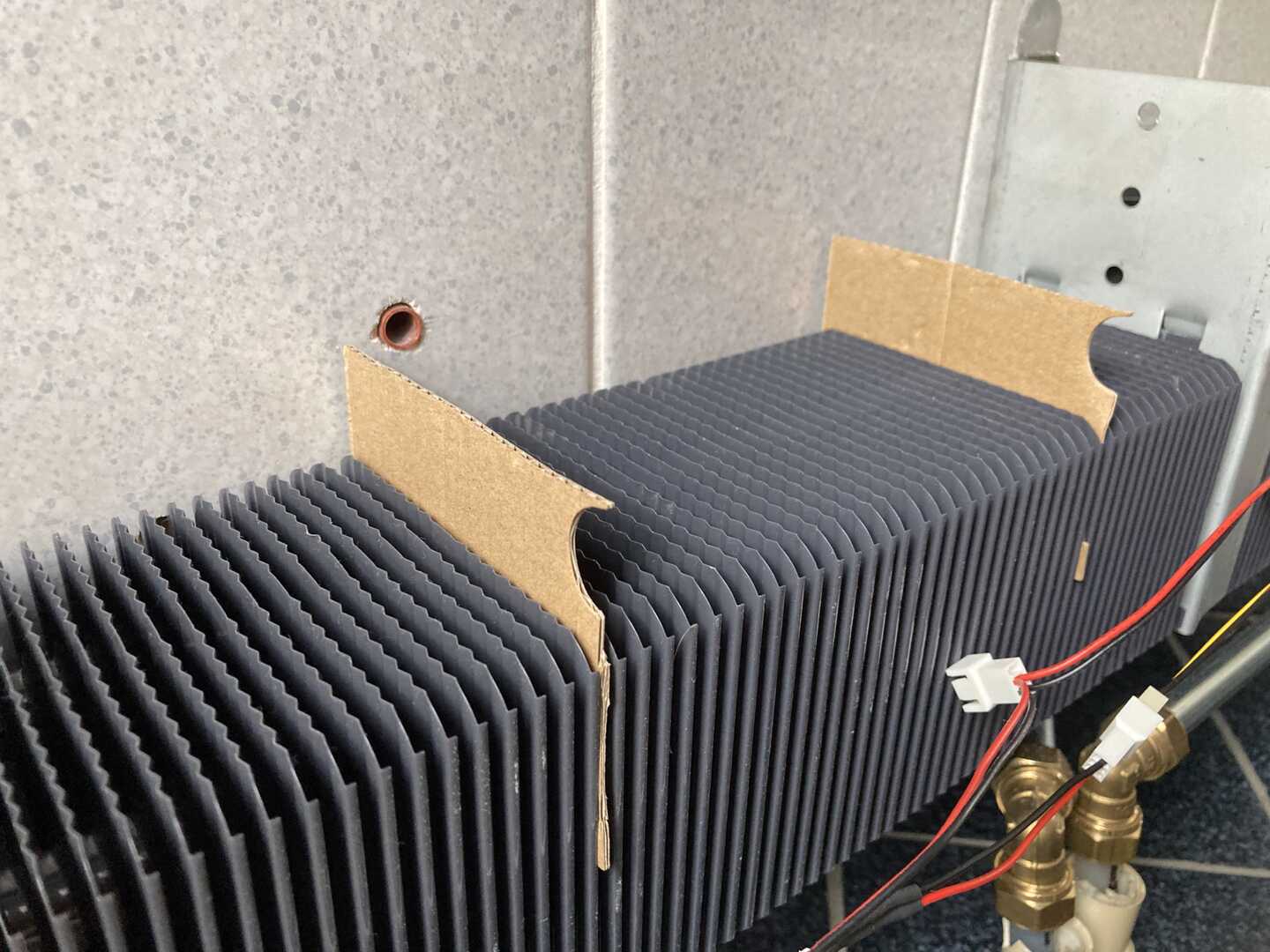
Cut cardboard to shape, place in between radiator grill blades
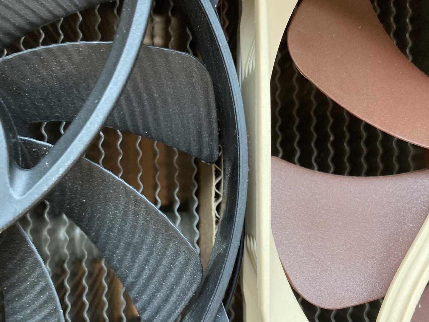
Place in between fans.
Place in between fans.
- Connect & power-up
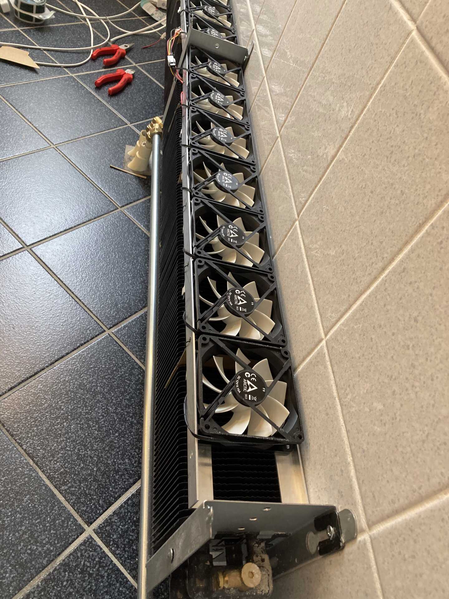
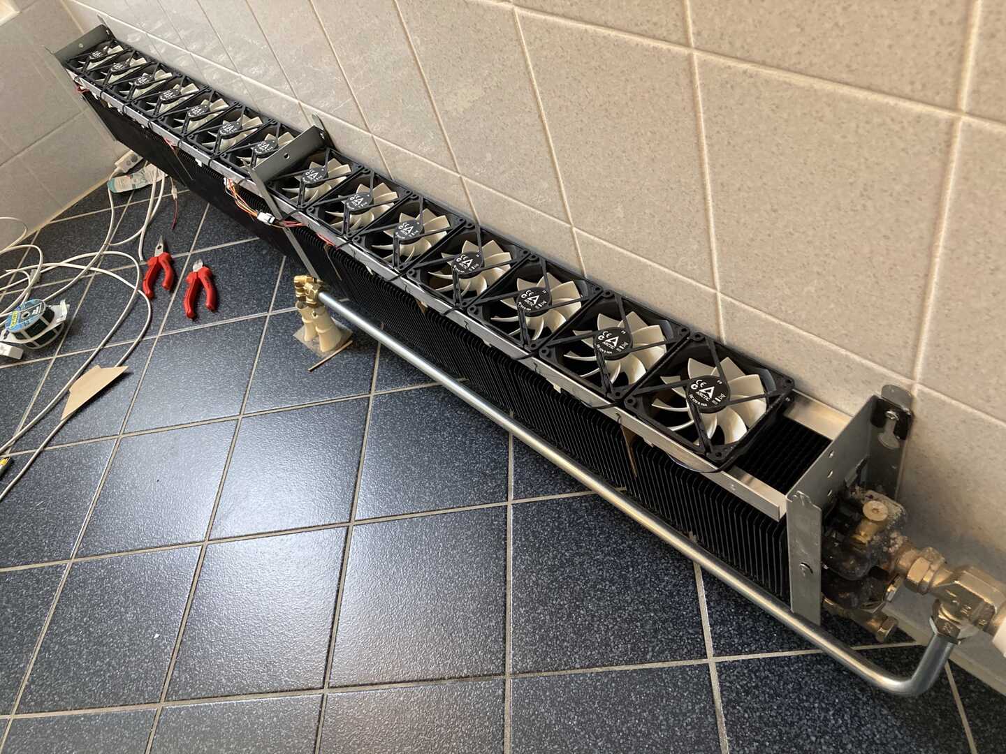
Fan array just before outer casing mounting.
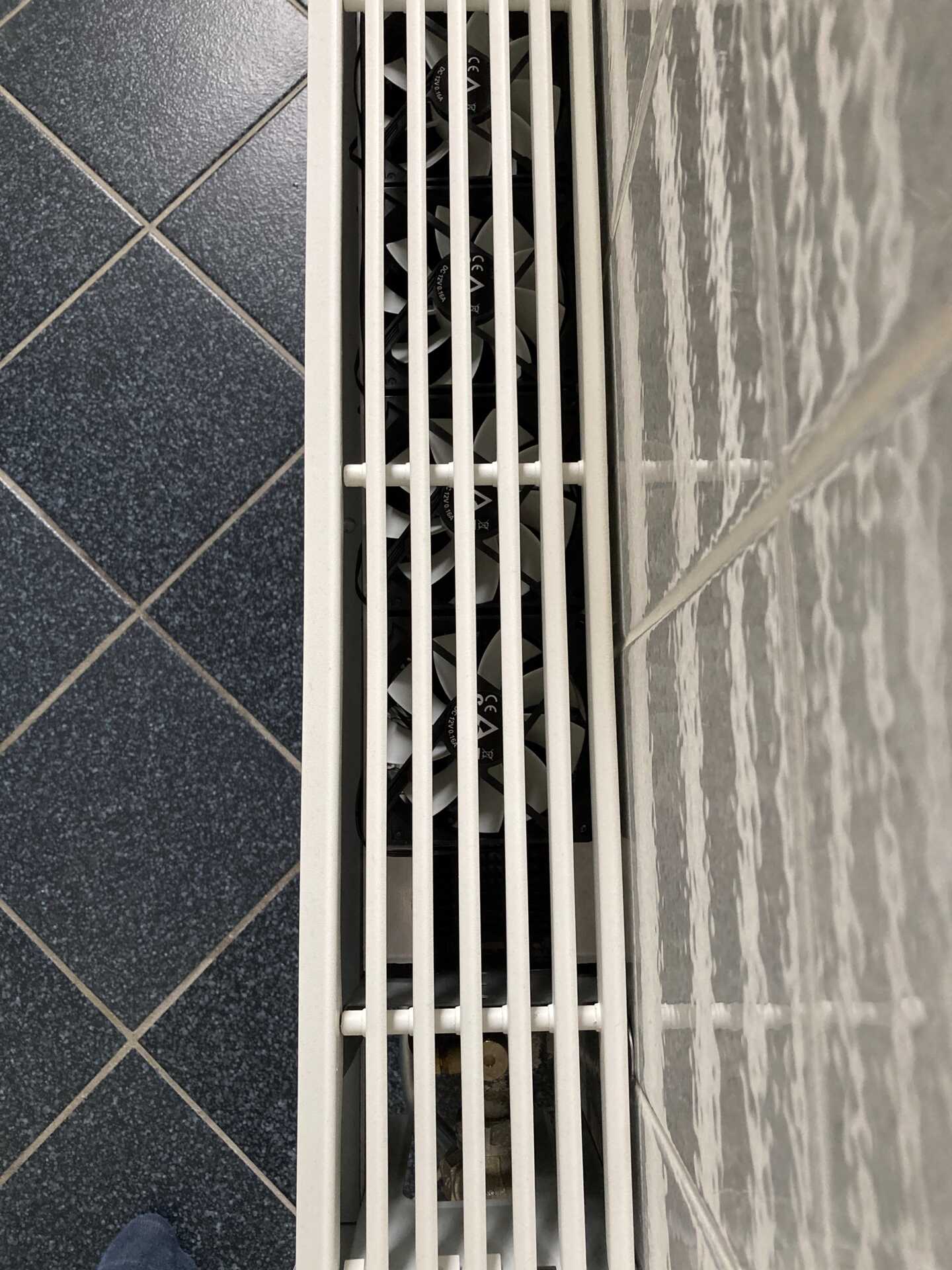
Fans are visible from the top, but barely noticable in daily life.
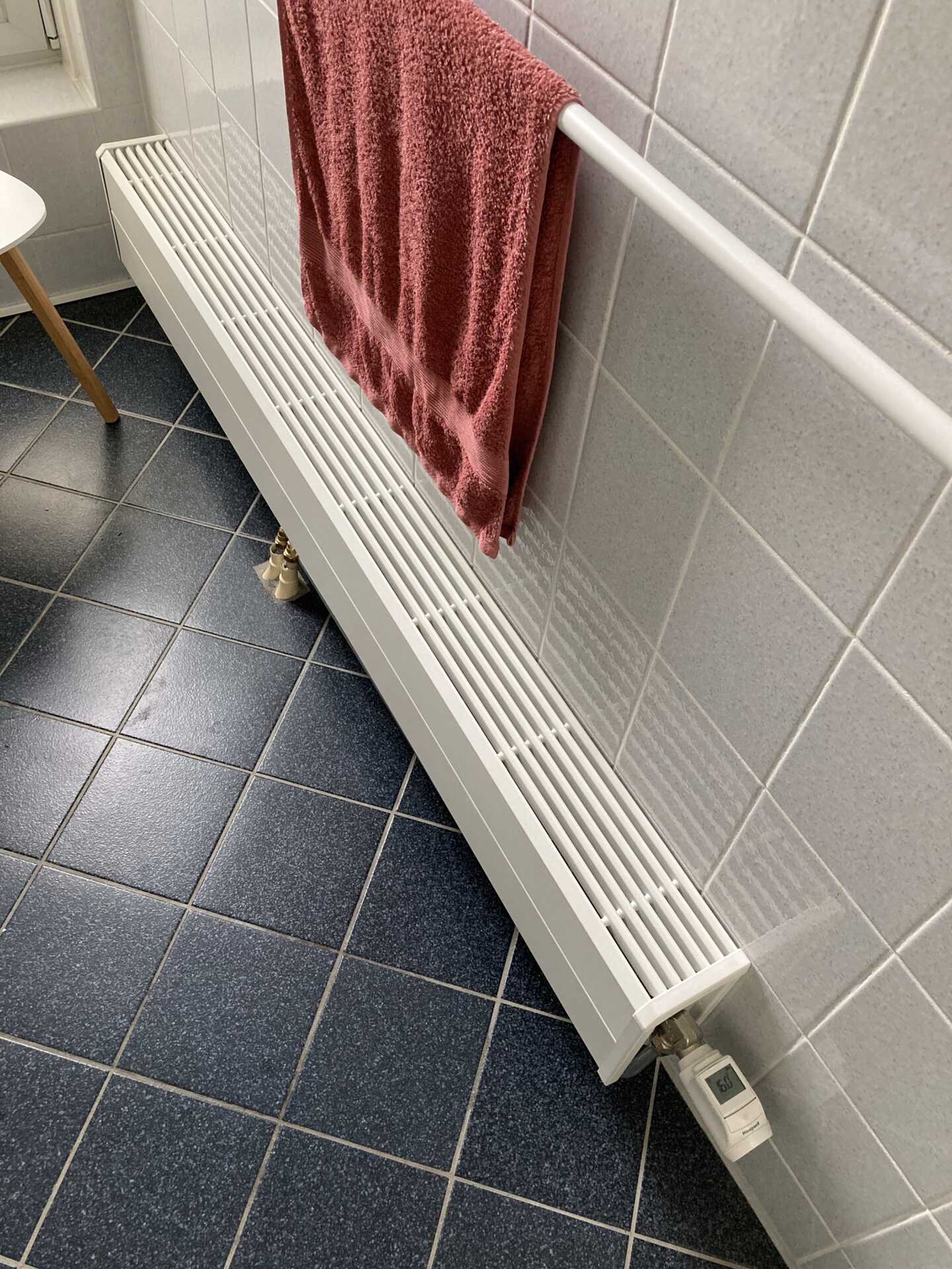
Final configuration. Towel not included.
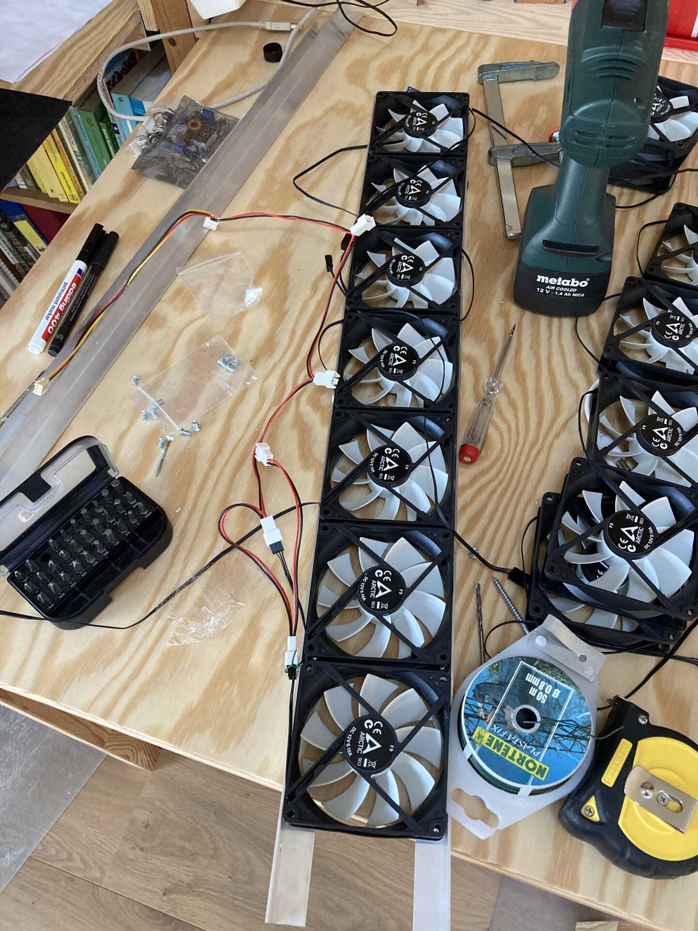
Hardware and design 
This is most of the hardware required to make the DIY DBE fan arrays. Power supply not shown.
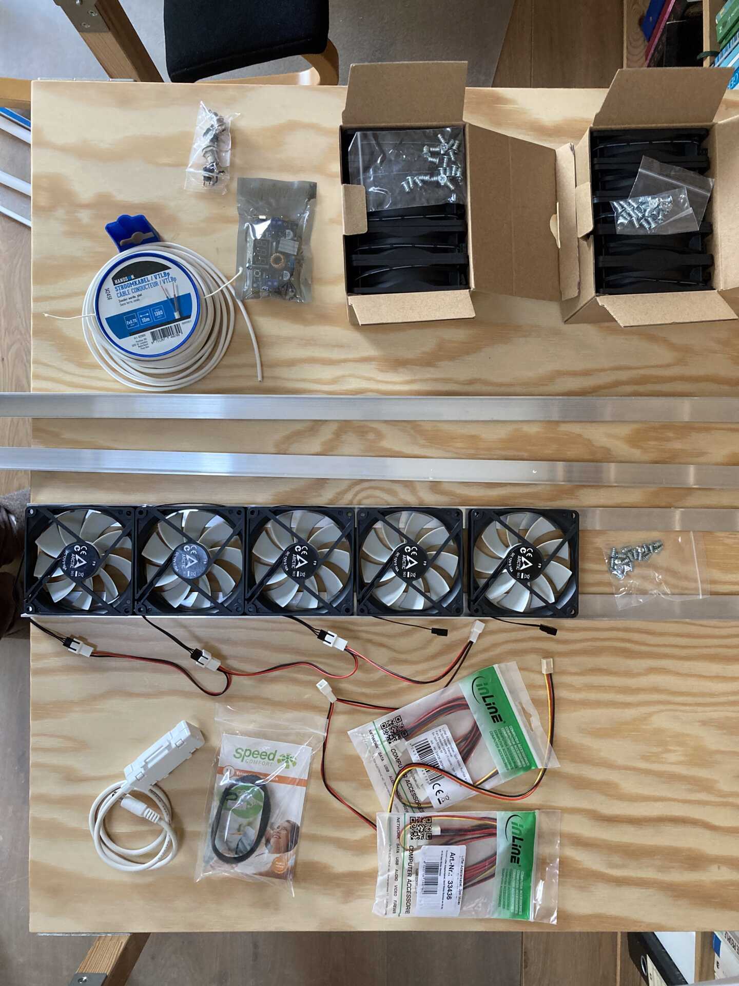
Bill of Materials 
For 2x 70 cm fan arrays, suitable for a 160cm Jaga radiator:
- 14x Arctic F9 fans (tweakers.net) (52€)
- 4m 20x20x2mm aluminium profiles (gamma.nl) (18€)
- 3x molex fan plug splitter (hardwarewebwinkel.nl) (12€)
- 1x XL4015 step-down converter (tinytronics.nl) (7€)
- 1x 12V >3A power supply, e.g. Seasonic SSA-0601HE-12 (tweakers.net) (20€)
- 1x Thermostat switch, e.g. this ready-made version (speedcomfort.nl), or solder one yourself
- 1x DC jack connector (tinytronics.nl), plastic is preferred for insulation
- Some power cable, I used 2x0.75mm^2 (gamma.nl) which might be a bit overkill but this saved me to investigate this (5€)
Total cost: 114€, plus shipping etc.
Fan throttling 
There are different methods to control fan speed (analog.com), e.g. using the fancy and optimal PWM, or using a blunt and simple voltage control. I settled for the latter for ease of use, as I can simple use a step-down converter (also called buck converter) to regulate my 12V input to anything from 0-12V.
Step-down requiremnets 
- Needs 17 * 2W = 35W @ 12V = 3A
- Efficient ideally >90%
- Accessible / easy voltage adjustment knob
Options:
- XL4015: 7 EUR, 96%, max 4A @ 32V, display. deltaU > 1.5V, Efficiency @ 12/5V * 5A = 87%
- XL4005: 3.5 EUR, 92%, max 5A @ 32V, needs cooling >25V. Efficiency @ 12/5V * 5A = 90%
- lm2596: 3 EUR, 92%, max 1A @ 35V, deltaU >1.5V.
- XL6009: 4 EUR, 94%, max 3A @ 32V, step up-down
Chose XL4015 because of high efficiency and display.
Fan requirement 
- Medium to high static pressure
- Low noise, <30 dB(A) at 10cm, preferably <20 dB(A)
- Low power, <1W per fan
- High MTBF, >100khrs
- Need low start-up voltage (e.g. able to run on at least 5V)
- PWM or ‘silent’ versions not required, simply under-volt.
Fans considered (see overview here (tweakers.net):
- Arctic F9 (tweakers.net): 4.0 EUR, 24dB, 60 m3/h, 1800 rpm, 1.35 mm H2O, fluid dynamic bearing, starting voltage: 2.6V, 1.9W
- Be quiet pure wings 2 92mm (tweakers.net): 9 EUR, 19dB, 56 m3/hr, 1900 rpm, rifle bearing @ 80khrs, 1.65 mm H2O, starting voltage 5V, 1.8W
- noiseblocker blacksilent xe-2 (tweakers.net), 8 EUR, 20dB, 65 m3/hr, 1800 rpm, 0.9 mm H2O, ?? Bearing @ 80 khrs, starting voltage 3.5V, 1.3W
- Enermax T.B.Silence 9cm (tweakers.net), 7 EUR, 13dB, 46 m3/hr, 1400 rpm, 1.2mm H20, twister bearing @ 160khrs, 1.8W,
I ordered each one of each, but did not notice too much of a difference in noise/airflow with an unscientific approach of listening by ear and feeling airflow with my hand. I therefore settled for the Arctic F9 fans for their low cost.
Temperature control 
I settled for a simple on/off thermostat which can switch my 12V input voltage. A more fancy control using temperature sensors, ESP8266, Wifi, MQTT etc. are all possible, which might provide slightly better performance, but I want my radiator to work when I turn the knob 🤓
Options found:
- Thermostaat 12v met schakelfunctie 10A (benselectronics.nl)
- Speedcomfort Thermostaatschakelaar (speedcomfort.nl)
I chose the Speedcomfort for my setup.
Power supply 
Requirements:
- High efficiency idle (<0.2W )
- Low noise, <30 dB(A) at 10cm, preferably <20 dB(A)
- Relatively high current (for worst-case 15 fans @ 0.2A we need 3A)
I had spare power supplies lying around, but else I would go for something from seasonic like this 60W Seasonic unit (tweakers.net). Unfortunately 3A @ 12V is slighly beyond the capabilities of adapter-type power supplies, so you get these brick-type supplies instead. Better safe than sorry.
Update: others do get away with a 3A 12V power adapter, so you might opt to use those. The advantage of a power brick is that you can position it away from a power socket, but of course it’s biger.
Construction considerations 
Fan frame 
I used aluminium profiles (20x20x2 mm^3) to hold the fans. This is light-weight yet sturdy, and relatively easy to saw/cut into shape yourself. For wider Jaga models (e.g. T20), you could use thin multiplex wood (e.g. 3.6mm) instead, which is slightly easier to saw/handle.
Optimal thermocouple positioning 
I tested a few locations to put the thermocouple, and in the end I compromised between optimal position (=fastest response) and accessibility (=easy monting). I mounted it on the pipes at the rear-end of the radiator. I tested the reponse and got the following results. It takes about 2-5 minutes after the central valve opens until the thermocouple is triggered. Not bad!
Timing:
- Evohome setpoint gateway to actuation: 2:30 min
- Actuation to return pipe temperature: 5:20 (1)
- Actuation to rear heat block temperature: 7:20 (2)
- Actuation to rear heat block pipe temperature: 7:20
Prototyping 
Before I made the above ‘industrialized’ version, I did some prototyping. Below a few pictures that might inspire others.